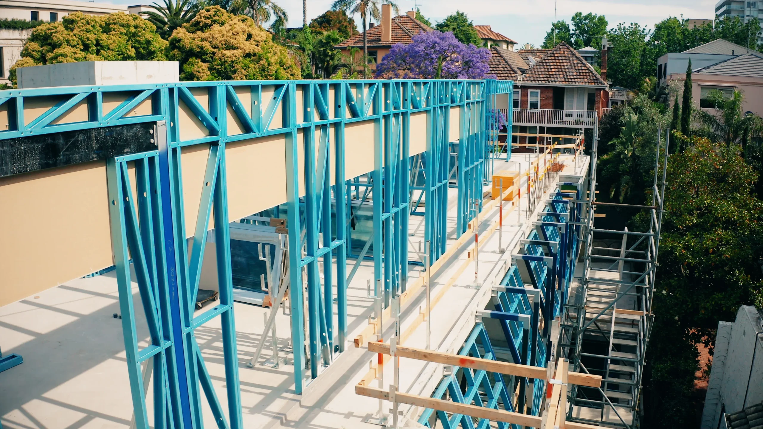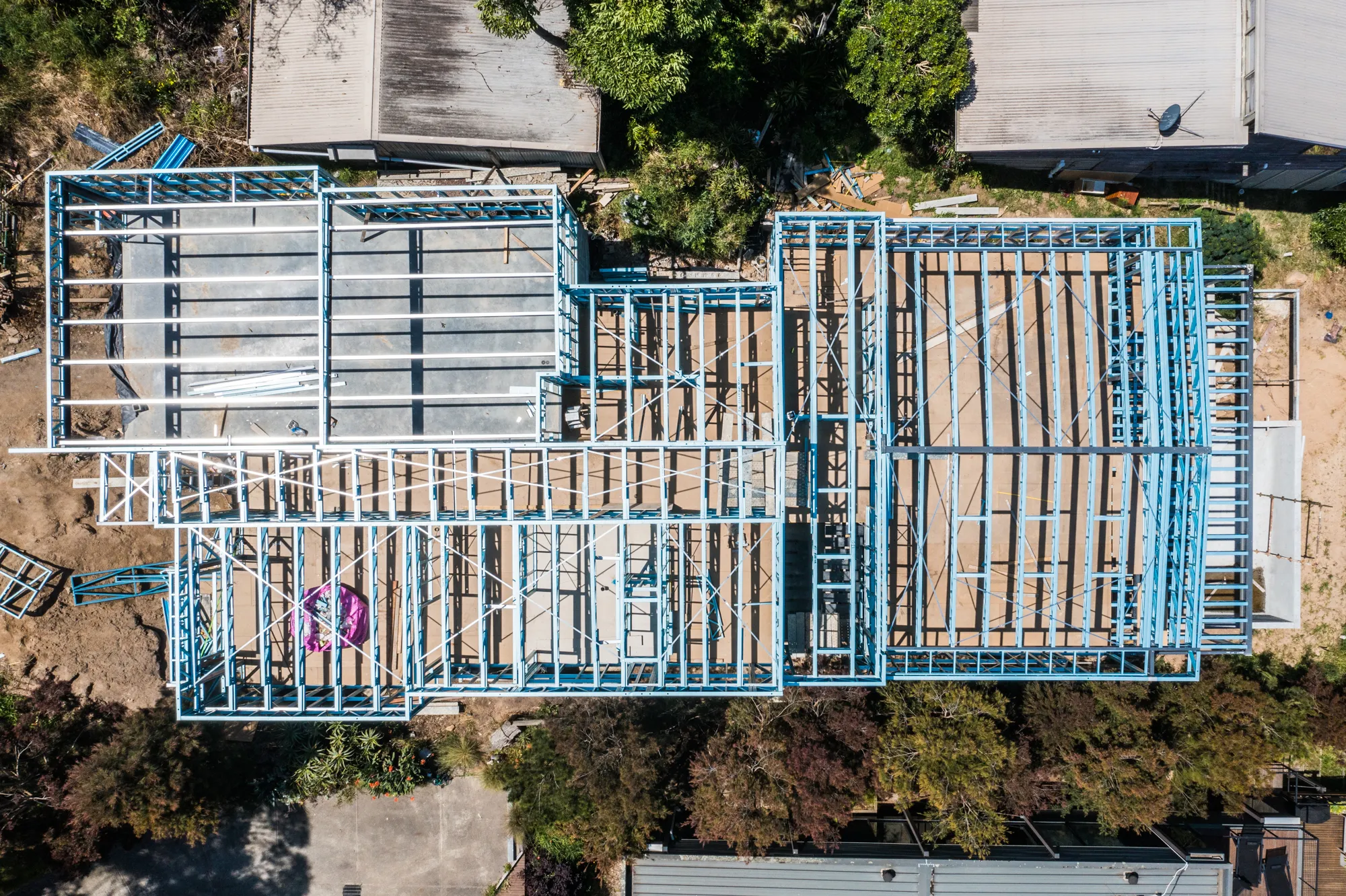


Steel frame erection drawings are the primary document that connects the engineering design to the physical installation of a steel frame on site. They tell the installation team where every panel goes, how it is oriented, what fixings are required, and how the completed frame should look from every elevation.
For builders who work regularly with steel frames, reading erection drawings becomes second nature. But for those encountering them for the first time, or working with a new supplier whose drawing format is unfamiliar, they can appear dense and technically demanding. Misreading an erection drawing is one of the most common causes of framing errors on site, and framing errors are expensive to fix once walls are lined and the build has progressed past the frame stage.
This guide explains what erection drawings contain, how to read the key elements, what the mark numbering system means, and how to use the drawings effectively on site. It is written for builders, site supervisors, and installation crews who work with light gauge steel frames supplied and designed by manufacturers like CMC Steel Solutions.
Understanding erection drawings also connects directly to understanding what makes a quality steel frame package. A supplier who produces clear, complete, and accurately mark-referenced erection drawings is demonstrating the same precision in their design process that flows through to the fabricated frames themselves.
Erection drawings are a set of technical drawings prepared by the steel frame manufacturer or their design team that show how the fabricated frame components are to be positioned and assembled on site. They are distinct from the architectural drawings prepared by the building designer, and they are also distinct from the structural engineering calculations prepared by the certifying engineer.
Where architectural drawings show what the building will look like and structural calculations confirm that the frame will perform adequately, erection drawings show how to put the frame together. They are the installation instructions for the frame package, and they must be read in conjunction with the physical frames delivered to site.
At CMC Steel Solutions, erection drawings are produced directly from the 3D BIM model used to design and engineer the frame. This means every dimension on the drawing corresponds to the actual geometry of the model, and every mark number on the drawing corresponds to a label on a physical frame component in the delivery. There is no translation step between the design and the drawing that could introduce errors.
Our overview of how 3D BIM modelling works in steel frame construction explains how the design and documentation process produces the erection drawings that arrive with your frame package.
A complete set of steel frame erection drawings for a residential or light commercial project typically consists of the following document types.
The mark numbering system is the most important practical tool in a steel frame erection drawing set. It is the bridge between the drawing and the physical frame on site, and understanding it is the foundation of reading erection drawings correctly.
Every wall frame panel, roof truss, floor joist, and structural element in a steel frame package is assigned a unique mark number during the design phase. That mark number is printed or stamped on the physical component during fabrication, and it appears on the erection drawing at the position where that component is to be installed.
Mark numbers in light gauge steel framing typically follow a convention that encodes information about the component type and location. A common format uses a prefix letter to indicate the component type followed by a sequential number. For example:
The specific convention varies between manufacturers. CMC Steel Solutions uses a mark numbering system that is consistent across all projects and is explained in the drawing legend included with every drawing set. Before reading the erection drawings on a new project, review the legend so you understand the mark prefix convention being used.
When a frame panel is delivered to site, locate its mark number on the label attached to the frame. Cross-reference that mark number to the floor plan view to find where the panel is installed. Then refer to the wall frame elevation drawing for that mark number to confirm the panel’s internal configuration and orientation before lifting it into position.
The wall frame elevation drawing is the most information-dense document in the erection drawing set. Here is how to read the key elements.
The roof truss layout plan shows the positions of all trusses in plan, viewed from above. Here is how to navigate the key information.
The most frequent errors that occur when reading steel frame erection drawings on site fall into a small number of recurring categories. Being aware of them helps installation teams avoid them.
For a broader overview of the framing errors that are most costly to fix once the build has progressed, our guide on common steel framing mistakes builders make and how to avoid them covers the full range of installation and procurement errors that experienced builders learn to avoid.
The erection drawings for a certified steel frame project are not just installation instructions. They are part of the compliance documentation that supports the Reg 126 structural engineering certificate issued for the project.
The structural engineer certifies that the frame, as designed and as shown in the erection drawings, meets the structural requirements of the applicable Australian standards. The certificate is issued against the specific frame design documented in the drawings. If the frame is installed differently from what the drawings show, the certificate may no longer accurately represent the as-built condition of the structure.
This is why it is important to follow the erection drawings precisely rather than making on-site decisions to vary the frame configuration without consulting the engineer or the framing manufacturer. Small departures from the drawings may seem inconsequential on site but can affect the compliance status of the frame and the validity of the structural certificate.
Our detailed guide on what a Reg 126 certificate is and why every steel frame build needs one explains the relationship between the engineering documentation and the as-built frame in more detail.
Occasionally, a discrepancy arises on site between what the erection drawing shows and what the delivered frame appears to require. This can happen for a number of reasons: a late design change that was not reflected in the drawing revision, a labelling error during fabrication, or a genuine manufacturing variation that needs to be investigated.
The correct procedure when a discrepancy is identified is to stop installation of the affected element and contact the framing manufacturer before proceeding. Do not attempt to modify the frame on site without the manufacturer’s written agreement. Do not substitute a different component from the delivery without confirming that it is interchangeable with the element specified in the drawings.
At CMC Steel Solutions, our design team is available to answer site queries about erection drawings and to issue revised drawings or written direction when a site issue requires a documented response. This support is part of our standard project service and ensures that any discrepancy is resolved correctly rather than through an undocumented on-site workaround.
Our guide on what steel frame building contractors in Melbourne do from design to installation explains how our project support process works from first contact through to final frame inspection.
Erection drawings are also the primary reference document for the frame inspection carried out by the building surveyor before the walls are lined. The surveyor uses the drawings to verify that the installed frame matches the certified design: that panels are in the correct positions, trusses are at the correct spacing, lintels are correctly seated, and bracing is installed as shown.
Having a clean, current set of erection drawings on site at the time of the frame inspection makes the inspection process faster and reduces the risk of inspection queries or hold points. If the surveyor identifies a discrepancy between the drawings and the installed frame, the drawings are the reference document for determining what corrective action is required.
Builders who understand and follow their erection drawings consistently typically have faster and less contentious frame inspections than those who treat the drawings as a reference of last resort.
Every steel frame package supplied by CMC Steel Solutions includes a complete set of erection drawings produced directly from the 3D BIM model used to design and engineer the frame. Drawings are mark-referenced, clearly dimensioned, and coordinated with the physical frames in the delivery. Our design team is available to answer site queries throughout the installation phase.
Contact us on 1300 285 566 or email info@cmcsteelsolutions.com.au to discuss your next project and find out how our documentation standards can make your frame installation faster, more accurate, and easier to certify.


Are you looking for steel framing solutions? We at CMC Steel Solutions offer wide range of products for construction projects.
Connect with our team at 1300 285 566 or email us your doubts on info@cmcsteelsolutions.com.au for better response.